Trusted design professionals since 1995
What’s Covered on This Page
- Signs a Part Design Isn’t Ready to Print
- Design Optimization vs. Reverse Engineering: Choosing the Right Starting Point
- When You Don’t Need Professional Design Optimization
- Inside a Design Review for Functional and Industrial Parts
- Engineering Validation and Sign-Off Before Field Use
- What files do I need to bring in for a design optimization review?
- How long does a design review take before my part is ready to print?
- Do I need design optimization or reverse engineering for my part?
- Do all 3D printed parts need a professional design review?
- Why did my part fail when it looked fine in the CAD file?
Signs a Part Design Isn’t Ready to Print
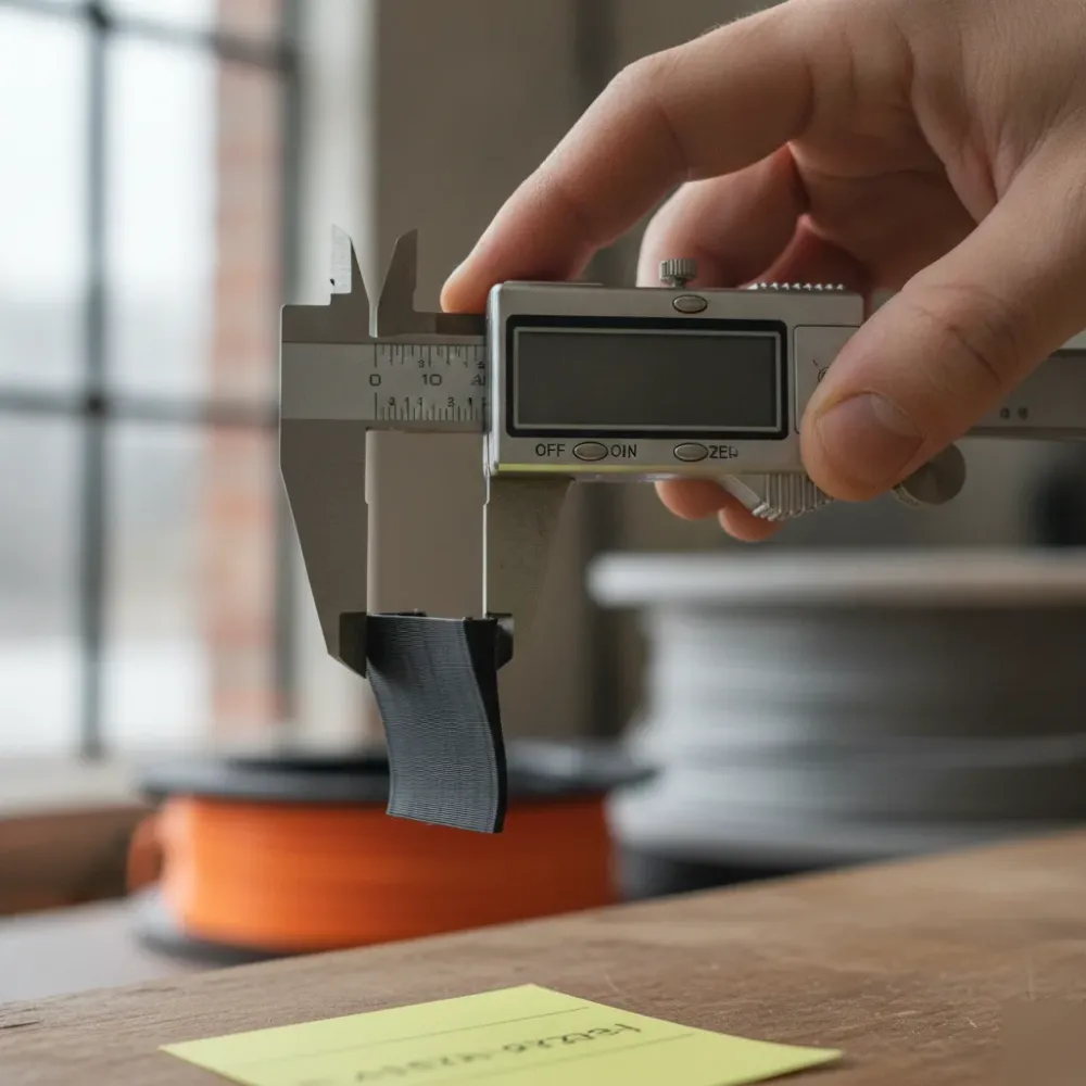
A model that looks fine on screen doesn’t always print fine. Walls thinner than a few millimeters tend to warp or fail outright. Overhangs steeper than roughly 45 degrees need support structures added, which changes the surface finish and adds extra post-processing. And tight-fit assemblies, say a pump skid bracket meant to bolt against an existing flange, can fail simply because the original tolerance never accounted for print shrinkage.
Reverse engineered parts bring their own set of risks. When a physical component gets captured through 3D scanning and converted to STEP or STL for printing, small surface noise from the scan can carry through into a rough or inaccurate print if it isn’t cleaned up first. Our team checks that point cloud to CAD conversion before it ever reaches the printer.
- Wall thickness below the printer’s minimum for the chosen material
- Overhangs or bridges without planned support structures
- Tight tolerance fits that don’t account for shrinkage or layer lines
- Sharp internal corners that concentrate stress on load-bearing parts
- File geometry with gaps or non-manifold edges from a rushed CAD export
None of these issues are hard to fix once someone catches them. That’s the whole point of a design review before printing: catch it on screen, not on the shop floor.
Design Optimization vs. Reverse Engineering: Choosing the Right Starting Point
Not every project that lands on our desk needs Design Optimization for Print. Some need Reverse Engineering, Physical-to-Digital instead, and knowing which one to ask for up front saves you a round trip.
Design Optimization for Print starts with a digital file that already exists. You bring us a STEP, IGES, or STL model, and our licensed engineers rework wall thickness, support structures, and orientation so the part prints cleanly on the first run. The file works fine on screen, it just wasn’t drawn with a printer in mind.
Reverse Engineering starts from a completely different point. There, we begin with a physical part, maybe a worn skid component or an obsolete pump housing, something with no drawing on record. We capture it with 3D laser scanning, convert the point cloud to CAD, and build the digital model from scratch.
- You have a CAD file already, but it fails or warps when printed: that’s Design Optimization for Print
- You have a physical part with no drawing, no CAD, no record: that’s Reverse Engineering, Physical-to-Digital
- You have a facility or site that needs documenting as-built: that falls under our scanning services, not either of these
- You’re not sure which file format you’re holding: send it over and we’ll confirm before quoting
Mixing these up costs time. We’ve seen procurement teams request optimization on a project that actually needed a full reverse engineering pass, because the geometry was too degraded to salvage as-is. Our team sorts this out during the estimate stage, not after the invoice lands.
If you’re not sure which service applies to your part, that’s a normal question to have, and it’s the first thing we clarify on any Free Estimate call.
When You Don’t Need Professional Design Optimization
Not every print job that comes through our Calgary shop needs a design review, and we’d rather tell you that upfront than charge you for something you don’t need. If you’ve got a simple bracket, a decorative planter, a cable clip, or a display stand that’s already printing cleanly on your desktop FDM machine, no warping, no failed layers, nothing load-bearing, there’s no reason to pay for professional optimization. Straightforward printing is the right call, and we’ll say so during a consultation instead of inventing a reason to sell you engineering work you don’t require.
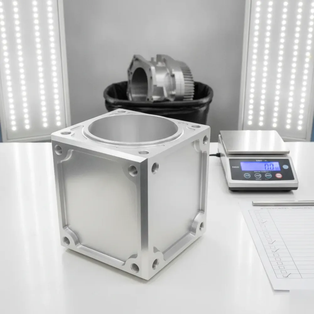
The factors we actually weigh are load, exposure, and consequence. A phone stand sitting on a desk in a Kensington apartment has none of the three. A drone mount that needs to survive vibration and impact, or a jig running on a production line in an industrial park near Foothills, has all three. When a part carries no mechanical stress, will never be reviewed by a building official or safety authority, and a failed print just means reprinting rather than putting a person or process at risk, professional optimization is more than the job calls for.
- Purely decorative or display items with no functional load, such as signage, models, or artistic pieces
- Prototypes still in the idea stage, where you’re testing form rather than final function
- One-off personal projects, garden hooks, cable organizers, hobby parts, that are already printing successfully
- Parts with no exposure to regulatory review, building codes, or safety certification requirements
- Low-consequence replacement parts where a failed print only costs a few hours and some filament
We run into this often with hobbyists, students, and small makers across Calgary who bring in files that are already dialed in. In those cases we recommend going straight to printing, sometimes with a quick check on material and orientation settings, but nothing more involved than that. Being upfront about when optimization isn’t necessary is just part of how we operate. It means that when we do recommend a full design review for a structural, load-bearing, or safety-relevant part, you can trust the recommendation is based on real risk, not on padding the invoice.
Thinking about Design Optimization for Print? Let’s talk.
Call now. Masters-3D is ready to help.
Inside a Design Review for Functional and Industrial Parts
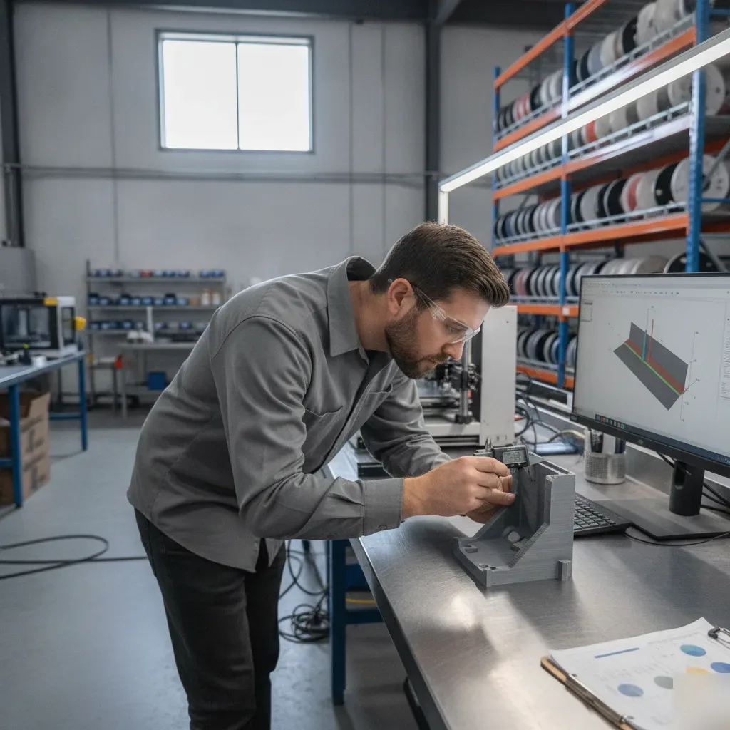
A design review kicks off the moment a client emails over a file or walks a physical prototype into a Calgary print shop. Instead of just slicing the model and hitting print, an experienced technician stops to ask what the part actually has to do. Will it sit under load inside a compressor housing, index against a jig on a CNC line, or seal against another component in a fluid system? That question about end use shapes everything downstream, since geometry that’s fine for a display piece can be completely wrong for something that has to survive vibration, heat, or repeated assembly cycles in an Alberta shop.
- Initial submission review: the file or physical part gets checked against the intended print process, whether that’s FDM, SLA, or SLS, since wall thickness and support strategy vary between them
- Geometry audit: overhangs, thin ribs, unsupported spans, and sharp internal corners get flagged as likely failure points
- Tolerance mapping: mating surfaces, bore diameters, and press-fit features are checked against real-world shrinkage and layer resolution, not just the numbers in the CAD file
- End-use stress check: expected loads, temperature exposure, and chemical contact are matched against material properties before anything gets scheduled to print
- Iteration and re-check: revised files run through the same review again until the part satisfies both manufacturability and functional requirements
For a simple bracket or fixture, one round of adjustments is often enough. But for anything load-bearing, safety-relevant, or headed for repeated mechanical use, clients should expect at least two or three iterations before the file gets locked in. That’s not a sign the part was designed poorly; it’s just the reality that 3D printing behaves differently than machining or injection molding, and small changes in wall thickness or orientation can shift strength and fit in meaningful ways. Shops that skip this step are the ones sending customers home with parts that crack on the first torque test.
This review process is what separates a print-only vendor from a concept-through-completion partner. Rather than treating the file as fixed and the print as the only service on offer, the shop treats the design itself as part of the deliverable, refining it alongside the client until the part performs as intended in its actual Calgary application, whether that’s on a factory floor, in a fabrication shop, or out in the field.
Engineering Validation and Sign-Off Before Field Use
Optimizing a design for print is only half the job when the part is headed for industrial equipment, a pressure vessel, or any safety-critical assembly. Alberta law doesn’t leave much room for interpretation here. The Engineering and Geoscience Professions Act, RSA 2000, c E-11, limits the stamping and formal sign-off of engineering drawings to individuals licensed through the Association of Professional Engineers and Geoscientists of Alberta, better known as APEGA. In practical terms, that means no matter how carefully a file has been tuned for wall thickness, infill strategy, or layer orientation, it can’t be legally certified for regulated equipment until a licensed professional engineer has reviewed and stamped it.
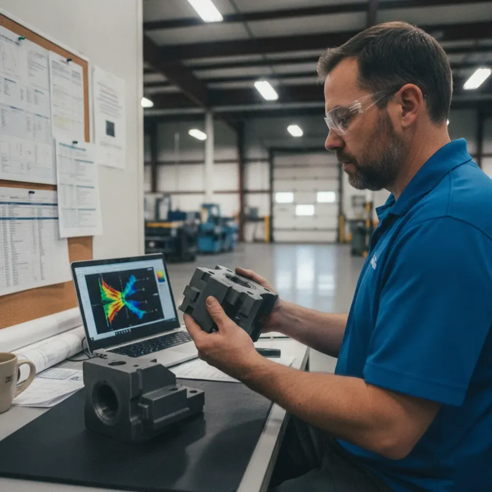
This is exactly where many Calgary manufacturers and fabrication shops get stuck. A third-party print optimization service might hand back a beautifully refined STL or STEP file, but if that shop has no APEGA-licensed engineer on staff, the client is left hunting for an independent stamp elsewhere, which adds weeks to the timeline and pulls in a second party who has no real feel for the original design intent. Masters-3D closes that gap by keeping licensed engineers on its core team, so optimization and sign-off happen under one roof, with one accountable point of contact.
For parts that will face pressure loading, elevated temperatures, or repeated mechanical stress, in-house validation usually runs through several concrete checks before any stamp gets applied.
- Finite element analysis to confirm the optimized geometry holds its structural margins under expected load cases
- Material property verification against the specific print process, resin, or filament used, since optimized wall thicknesses can behave differently from one material batch to the next
- Review of layer orientation and print path against known failure planes for the part’s intended stress direction
- A documentation package suitable for client engineering files, audits, or insurance requirements
- Formal APEGA stamp and sign-off, applied only once the design meets applicable Alberta safety codes
This distinction carries the most weight for oil and gas service components, custom pressure fittings, and load-bearing brackets headed for plant floors across Calgary and southern Alberta, where a missing or invalid engineering stamp can stop a project cold during inspection or void insurance coverage altogether. Working with a provider that combines print optimization expertise with licensed engineering sign-off takes that risk off the table before the part ever reaches the field.
Frequently Asked Questions
Common questions about Design Optimization for Print
What files do I need to bring in for a design optimization review?
You need your existing CAD file, usually a STEP, IGES, or STL. Our engineers open that file first and check wall thickness, overhangs, and fit tolerances against what your printer can produce. If you’re not sure which format you have, just send it over. We’ll confirm the file type before we quote anything. If your part has no digital file at all, that’s a different service called reverse engineering, and we’ll flag that during the same call.
How long does a design review take before my part is ready to print?
Most reviews happen during the estimate stage, before any printing starts. Our licensed engineers check wall thickness, overhang angles, and tight-fit tolerances against your chosen material, then send back flagged issues for you to approve. This catches problems on screen instead of on the shop floor. Timelines depend on how complex the geometry is, but the goal is always the same: fix it before it becomes a failed print or wasted material.
Do I need design optimization or reverse engineering for my part?
It depends on whether you already have a digital file. If you have a CAD file that fails or warps when printed, that’s design optimization. If you have a physical part with no drawing on record, like a worn pump housing, that’s reverse engineering instead. We sort this out during the estimate call, not after you’ve paid for the wrong service. If you’re unsure which one applies, that’s a normal question to bring to us.
Do all 3D printed parts need a professional design review?
No, plenty of parts don’t need one at all. A cable clip, planter, or display stand that’s already printing cleanly on a desktop machine doesn’t need optimization. We weigh load, exposure, and consequence before recommending a review. A phone stand on a desk has none of those risks. A drone mount or a production jig running in an industrial park near Foothills has all three, which is when a design review earns its cost.
Why did my part fail when it looked fine in the CAD file?
Geometry that looks fine on screen doesn’t always survive printing. Walls thinner than a few millimeters tend to warp or fail outright, and overhangs steeper than roughly 45 degrees need support structures added, which changes the finish. Tight-fit assemblies can also fail if the original tolerance never accounted for print shrinkage. A design review catches these issues before the part hits the printer, so you’re not troubleshooting scrap on the shop floor.
Recent Comments