Trusted design professionals since 1995
What’s Covered on This Page
- What a 3D Piping Drawing Delivers
- From Scan Data to Finished Piping Model
- Engineering Sign-Off and Stamped Drawings
- When Existing As-Builts Are Not Enough
- Industrial Piping Projects Across Calgary
- Do you handle 3D piping drawing projects across the Calgary area, including lease sites and gas plants?
- What happens when your team arrives on site to scan a piping system?
- Why don’t the drawings for my older Calgary facility match what’s in the field?
- What file formats will I receive with my 3D piping drawings?
- How long does it take to get a stamped piping drawing set after the scan?
- Can a 3D piping drawing replace my facility’s outdated as-built records?
What a 3D Piping Drawing Delivers
We build every 3D piping drawing from point cloud data captured on site, then turn that data into usable CAD geometry. Depending on what the client’s downstream software needs, we’ll work in point cloud, E57, STEP, IGES, or DWG. That flexibility matters when a pipeline alignment sheet has to move from our scanning team to a fabrication shop without picking up a translation error along the way.
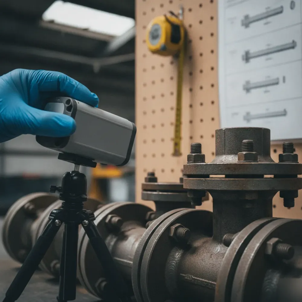
A pump skid or compressor package on an Alberta lease site rarely still matches its original design drawings after years of field modifications. So the real deliverable isn’t just a drawing, it’s an accurate as-built record. We validate every dimension against the scan data before a drawing ever gets our engineer’s stamp.
- Isometric piping drawings with dimensioned spool details
- Plot plans and P&IDs referenced to site coordinates
- CAD files in STEP, IGES, or DWG for fabrication use
- Point cloud or E57 data for archival and future reference
- Stamped, engineer-validated drawing sets for regulatory or client sign-off
This isn’t paperwork for its own sake. It’s the record a fabrication shop trusts before cutting metal.
From Scan Data to Finished Piping Model
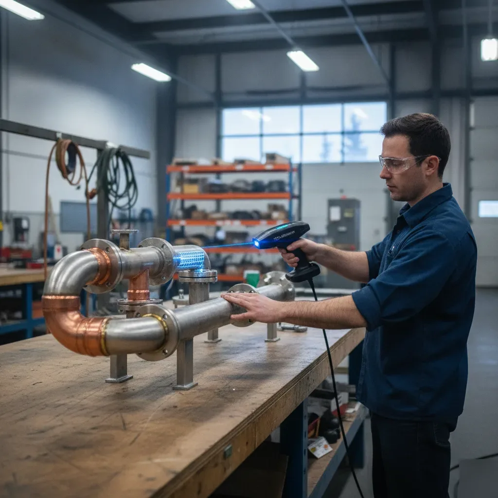
Every 3D piping drawing we produce in Calgary starts with a point cloud, not a guess. Our team laser scans the site or unit, then registers that data into a single coordinate system precise enough to catch a misaligned flange or a pipe rack that’s out of plumb. From there, our engineers convert the point cloud into a working model, checking wall thickness, elevation, and bore size against the scan before a single line goes into the drawing.
Modeling comes next. We build the piping in 3D, matching real-world routing, supports, and tie-ins instead of redrawing from memory or an outdated P&ID. This is the step that decides whether prefabrication goes smoothly. A pipe spool cut from a model that doesn’t match the field means rework, and rework costs money and time on site.
- Point cloud registration and cleanup (delivered as E57 or RCP)
- 3D piping model built to match scanned field conditions
- Isometric and orthographic drawings for fabrication and construction
- STEP or IGES files for downstream CAD integration
- Engineering review and stamped, validated final drawing set
The last step is where our in-house licensed engineers sign off. A stamped drawing means someone with real engineering accountability has checked the model against code and field conditions. That’s the difference between a drafted drawing and one you can actually build from with confidence.
Engineering Sign-Off and Stamped Drawings
Every 3D piping drawing we produce for a Calgary project passes through licensed engineering review before it leaves our shop. That review checks pipe routing, flange ratings, support spacing, and clash points against the original scan data. It’s not a formality, it’s the step that separates a drawing you can build from and one you have to verify on site.
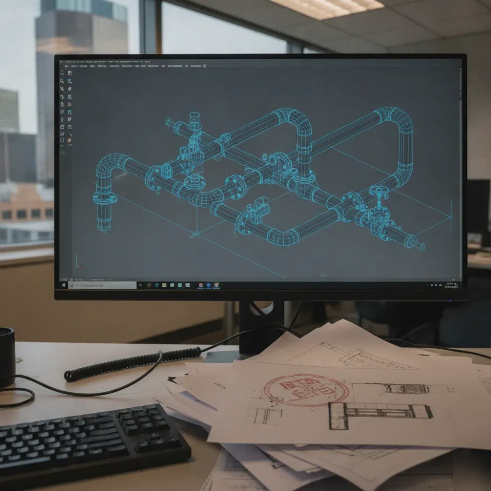
Stamped drawings carry weight.
Once a model passes review, our engineers apply their stamp to the final drawing set. That stamp confirms the geometry, tolerances, and dimensions meet engineering standards, and it gives your procurement and fabrication teams a document they can act on without a second round of field checks. We work in metric with imperial in brackets throughout, so a nominal pipe size might read as 100 mm (4 in.) on the same sheet your crew already uses.
So what actually lands in your inbox? A typical stamped package includes several file types, matched to how your team will use them.
- Stamped PDF drawing sets for permitting and field reference
- DWG piping isometrics for fabrication and construction
- STEP or IGES 3D models for downstream CAD work
- Point cloud or E57 data tied back to the original scan for verification
This matters most on skid packages, tank tie-ins, and battery site piping, where a missed elevation or an unflagged clash turns into rework at the fabrication shop. And that rework always costs more than the drawing would have. Our QA workflow catches those issues before the stamp goes on, not after the pipe’s already cut.
When Existing As-Builts Are Not Enough
Most Calgary facilities built before the 2000s have as-built drawings that no longer match what’s actually in the field. Piping gets rerouted during turnarounds, supports get added after a vibration issue, and none of it ever makes it back onto the original drawing set. We see this constantly on lease sites and older gas plants around the Calgary region, where decades of tie-ins and modifications sit undocumented.
Working from an outdated drawing is worse than working from no drawing at all. Crews assume it’s correct, then discover the clash in the field. That means rework, schedule slip, and budget overruns nobody planned for.
- Piping routes on paper do not match physical spool locations
- Support spacing or elevations were changed during past repairs
- Original drawings were lost, damaged, or never fully completed
- New equipment tie-ins were never added to the drawing set
- Multiple revisions exist with no clear record of which is current
When we hit any of these conditions, we don’t guess. Our team runs a 3D laser scan of the piping and structure, capturing actual field geometry to millimeter-level accuracy. That point cloud data, delivered in formats like E57 or RCP, becomes the foundation for a new CAD model in STEP or DWG.
The result is a drawing set that reflects reality, not history.
And because our in-house licensed engineers review and stamp the final 3D piping drawings, the package can be used directly for prefabrication, tie-in planning, or regulatory submission. No second round of field verification needed, and no assumptions carried forward from a drawing that was already wrong.
Watch Our Video
See How We Handle 3D Piping Drawings in
Masters-3D
Industrial Piping Projects Across Calgary
We produce 3D piping drawings for lease sites, batteries, and compressor stations across the Calgary region, from Foothills Industrial to sites out along Highway 2A. Calgary’s freeze-thaw cycle puts real stress on above-ground piping runs, so pipe supports and expansion loops need to be modeled accurately before fabrication starts. Our team works from point cloud scans or existing P&IDs to build a drawing set that matches what’s in the field, not what an old as-built says.

Most of our piping drawing work ties into a broader project: a tank farm expansion, a pump skid retrofit, a compressor or gen set package that needs new piping routed around existing structural steel.
Deliverables on a typical piping drawing package include:
- Isometric and orthographic piping drawings in DWG or PDF
- 3D models exported to STEP or IGES for downstream fabrication use
- Point cloud reference data in E57 or RCP where scanning was used
- Line lists and material call outs coordinated with the P&ID
- Stamped drawing sets signed off by our licensed engineers
That stamp matters. A drawing without engineering sign-off is a suggestion, not a fabrication document. We validate pipe supports, wall thickness, and routing clearances before the set goes out, which cuts down on field fit-up problems and change orders on site.
And that’s the whole point of doing this right the first time. Rework on a piping tie-in costs more than the drawing ever would.
Frequently Asked Questions
Common questions about 3D Piping Drawings
Do you handle 3D piping drawing projects across the Calgary area, including lease sites and gas plants?
Yes, we scan and model piping for facilities across the Calgary area, including lease sites and older gas plants. Our team travels to your site with laser scanning equipment to capture the piping and structure directly. This works well for skid packages, tank tie-ins, and battery sites where the piping has changed over the years. We build the drawing from what’s there, not from outdated paperwork sitting in a filing cabinet.
What happens when your team arrives on site to scan a piping system?
Our team sets up laser scanning equipment and captures the piping, supports, and structure in a single coordinate system. This step usually takes a few hours to a day, depending on the size of the unit or facility. We check for things like misaligned flanges and pipe racks that are out of plumb while we’re on site. Nothing gets modeled from memory. Every measurement comes from the scan data we collect that day.
Why don’t the drawings for my older Calgary facility match what’s in the field?
This happens because piping gets rerouted and supports get added during turnarounds, but the changes rarely make it back onto the original drawing set. It’s common on lease sites and older gas plants around Calgary that have seen decades of tie-ins and repairs. Working from those old drawings can be worse than having no drawing at all, since crews assume they’re correct until a clash shows up in the field. A new scan-based model fixes that gap.
What file formats will I receive with my 3D piping drawings?
You’ll receive files matched to how your team plans to use them, including STEP, IGES, or DWG for CAD work, plus point cloud or E57 data for archival. Isometric drawings with dimensioned spool details go to fabrication shops, and stamped PDF sets go to procurement or permitting teams. We also deliver plot plans and P&IDs referenced to site coordinates. This mix means your fabrication shop and your engineering team both get what they need from one project.
How long does it take to get a stamped piping drawing set after the scan?
Timeline depends on the size of the piping system and how many drawings your project needs, but every set goes through the same steps: scan, model, engineering review, and stamp. Our licensed engineers check pipe routing, flange ratings, and clash points against the scan data before applying their stamp. That review step is what makes the drawing something your fabrication team can act on without a second round of field checks.
Can a 3D piping drawing replace my facility’s outdated as-built records?
Yes, a scan-based 3D piping drawing gives you an accurate record that replaces as-builts that no longer match the field. This matters most for facilities where support spacing changed, new equipment was tied in, or the original drawings were lost or never finished. Instead of guessing which revision is correct, you get one drawing set built from millimeter-level scan data and backed by an engineering stamp.
Recent Comments